INA226 is a popular microchip to measure the voltage and power consumption that uses i2c digital interface. There are a lot of articles describing how to make it work with Arduino, much fewer about how it can be connected and read using generic Linux i2c tools and seems to be none explaining how can it be paired with Linux ina2xx kernel driver so it can be manipulated via hwmon subsystem. Let’s fix ths!
In this example we are going to:
- Enable i2c interface in Raspberry Pi OS
- Connect INA226 breakout board to Raspberry Pi zero 2w
- Create and enable a custom Device Tree overlay for OS to recognize the sensor
- Explore the sysfs entries provided by ina2xx kernel driver
Enable i2c interface
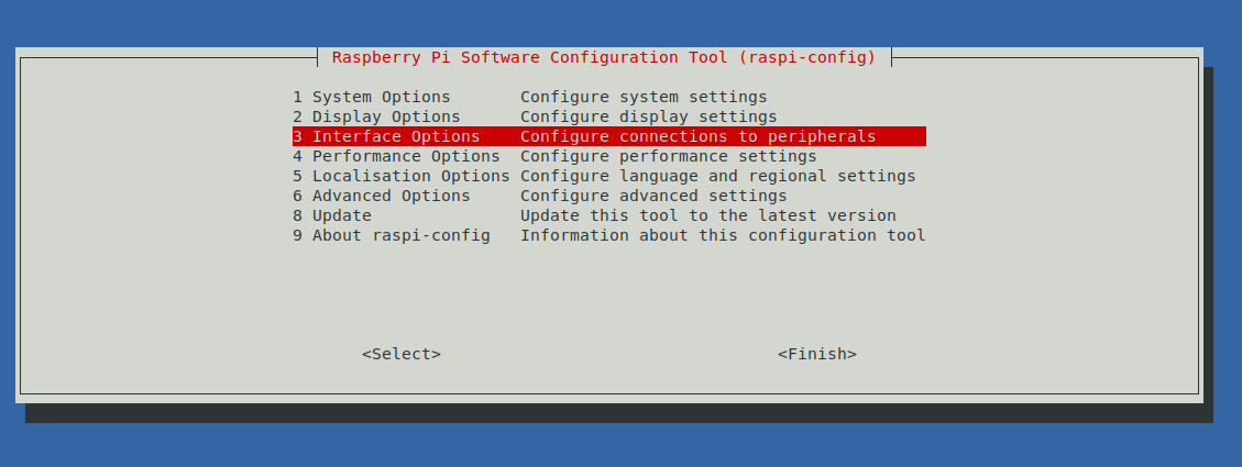
In Raspberry Pi OS (Debian) i2c interface is disabled by-default, so we obviously need to enable it first. To do that, open the shell on Raspberry and run
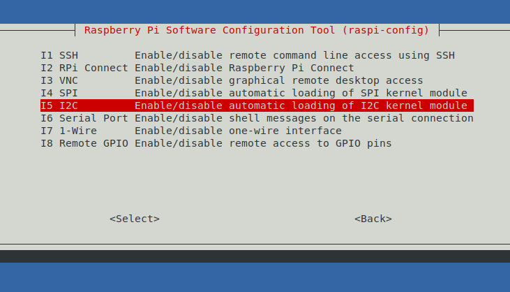
sudo raspi configIn UI select “3 Interface Options”
then I5 I2C
And in the next screen select “yes”
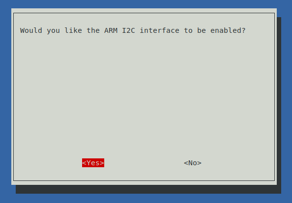
When done, you should be able to see at least 2 i2c devices:
$ ls /dev/i2c*
/dev/i2c-1  /dev/i2c-2
One of them is system internal, but i2c-1 is the one that is accessible via the GPIO pins 3 and 5.
You can now install the tools to inspect the i2c on Linux:
sudo apt install i2c-toolsAnd try to see if there are any devices connected to i2c bus:
$ sudo i2cdetect -y 1
     0  1  2  3  4  5  6  7  8  9  a  b  c  d  e  f
00:                         -- -- -- -- -- -- -- --
10: -- -- -- -- -- -- -- -- -- -- -- -- -- -- -- --
20: -- -- -- -- -- -- -- -- -- -- -- -- -- -- -- --
30: -- -- -- -- -- -- -- -- -- -- -- -- -- -- -- --
40: -- -- -- -- -- -- -- -- -- -- -- -- -- -- -- --
50: -- -- -- -- -- -- -- -- -- -- -- -- -- -- -- --
60: -- -- -- -- -- -- -- -- -- -- -- -- -- -- -- --
70: -- -- -- -- -- -- -- --
If it looks this way, it means no devices are connected which is expected.
Connecting the INA226 brealout board
The board we are going to use looks like this:
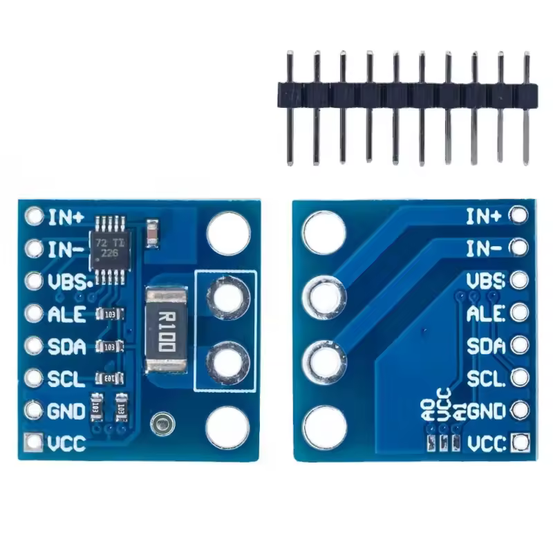
it has the shunt resistor that says “R100” which means 0,1 Ohm and it has following outputs:
- VCC – the + of the voltage that’s going to power the microchip. We are going to connect it to Raspberry pin nr 1 (3,3 V) or 2 or 4 (5 V). This chip can be powered by any of them since it can be powered by a voltage in range 2.7 – 5.5V
- GND – should be connected to the ground of both Raspberry and device under test. You can use any ground pin, say 6 or 9 or 14.
- SCL – the “clock” lane of i2c interface, should be connected to pin nr 5
- SDA – the “data” lane of i2c, should be connected to pin nr 3
- ALE – alert trigger – we leave not connected for now
- VBS – the Vbus – should be connected to the + of the power supply of the device under test, it is used to measure the power source supply voltage
- IN+ and IN- – will be installed sequentially in the supply line of the device under test (IN+ closer to the “+” of the power supply and IN- closer to the “-“). The INA226 can be installed in both high (between the device and “+” of power supply) and low (between the device and “-” of the power supply / ground)
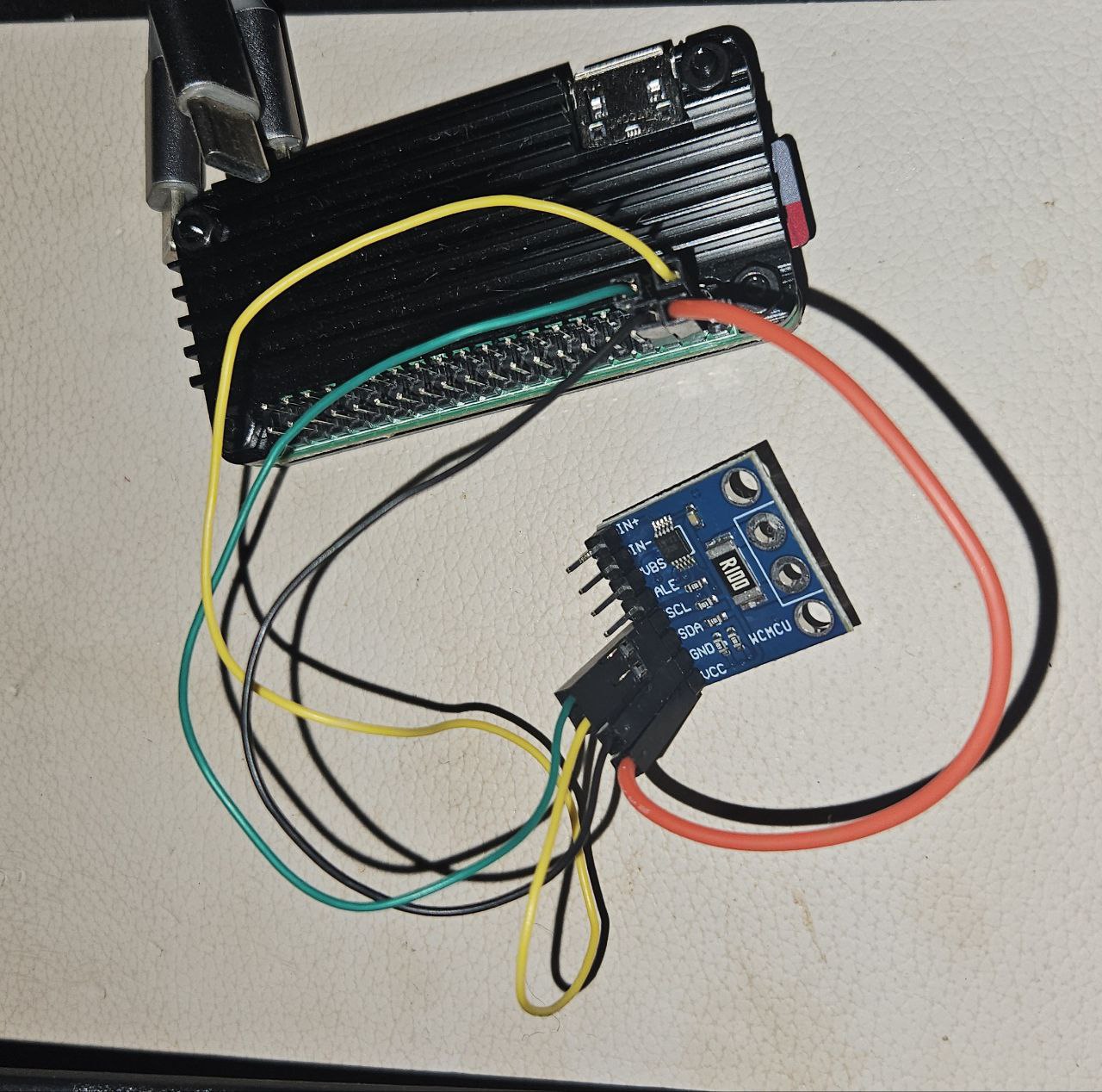
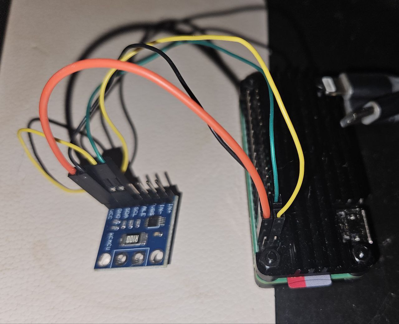
As soon as GND, VCC, SCL and SDA are connected (on this picurre – to the pins 6, 4, 3, 2 accordingly), Linux should be able to detect a new device on i2c bus:
$ sudo i2cdetect -y 1
     0  1  2  3  4  5  6  7  8  9  a  b  c  d  e  f
00:                         -- -- -- -- -- -- -- --
10: -- -- -- -- -- -- -- -- -- -- -- -- -- -- -- --
20: -- -- -- -- -- -- -- -- -- -- -- -- -- -- -- --
30: -- -- -- -- -- -- -- -- -- -- -- -- -- -- -- --
40: -- -- -- -- 44 -- -- -- -- -- -- -- -- -- -- --
50: -- -- -- -- -- -- -- -- -- -- -- -- -- -- -- --
60: -- -- -- -- -- -- -- -- -- -- -- -- -- -- -- --
70: -- -- -- -- -- -- -- --
We can see that the i2c device address on this case is 0x44. We need to remeber this – we are going to use it on the next step.
Custom Device Tree overlay
We can already use the i2c device as-is using generic i2c or SMBUS using, eg this python tool: https://github.com/e71828/pi_ina226. However, Linux kernel already includes a special kernel driver for ina2xx series of chips (docs, source, bindings) which is exposed via hwmon subsystem. However, we would have to define the i2c-connected INA226 in the Device Tree overlay for it to be recognized by kernel.
Devicetree is a way to describe all the hardware so operaing system can see what hardware is available on the current machine. Those trees are declared using a declarative language and compiled to a binary form using dtc compiler. The device tree binary that describes the current machine lies in the /boot/firmware directory as one of .dtb files. For Raspberry pi Zero 2w it is in the bcm2710-rpi-zero-2-w.dtb file.
The binary dtb file can be decompiled to a dts format (some meta-info would be lost though):
dtc -I dtb -O dts /boot/firmware/bcm2710-rpi-zero-2-w.dtb | lessIn the output of the decompiler, you should find the entries describing i2c interface:
/ {
        compatible = "raspberrypi,model-zero-2-w\0brcm,bcm2837";
<..>
        aliases {
<..>
                i2c0 = "/soc/i2c0mux/i2c@0";
                i2c1 = "/soc/i2c@7e804000";
                i2c10 = "/soc/i2c0mux/i2c@1";
                i2c = "/soc/i2c@7e804000";
<..>
                i2c2 = "/soc/i2c@7e805000";
        };

        soc {
<..>
                i2c@7e205000 {
                        compatible = "brcm,bcm2835-i2c";
                        reg = <0x7e205000 0x200>;
                        interrupts = <0x02 0x15>;
                        clocks = <0x08 0x14>;
                        #address-cells = <0x01>;
                        #size-cells = <0x00>;
                        status = "disabled";
                        clock-frequency = <0x186a0>;
                        phandle = <0x1b>;
                };
<..>
                i2c@7e804000 {
                        compatible = "brcm,bcm2835-i2c";
                        reg = <0x7e804000 0x1000>;
                        interrupts = <0x02 0x15>;
                        clocks = <0x08 0x14>;
                        #address-cells = <0x01>;
                        #size-cells = <0x00>;
                        status = "disabled";
                        pinctrl-names = "default";
                        pinctrl-0 = <0x15>;
                        clock-frequency = <0x186a0>;
                        phandle = <0x2a>;
                };
<..>
                i2c@7e805000 {
                        compatible = "brcm,bcm2835-i2c";
                        reg = <0x7e805000 0x1000>;
                        interrupts = <0x02 0x15>;
                        clocks = <0x08 0x14>;
                        #address-cells = <0x01>;
                        #size-cells = <0x00>;
                        status = "disabled";
                        clock-frequency = <0x186a0>;
                        phandle = <0x19>;
                };
<..>
                i2c0mux {
<..>
                };
If you can’t find the right “dtb” file, you can try to browse the sysfs representation of currently active device tree:
ls /sys/firmware/devicetree/base/Since we remember from the i2cdetect that INA226 resides on i2c bus number 1, we see in aliases section that i2c1 = "/soc/i2c@7e804000" it has address i2c@7e804000. So, let’s write and device tree overlay for the i2c@7e804000 section, given we know from i2cdetect that it has address “44”:
$ nano ~/ina226-overlay.dts

/dts-v1/;
/ {
    fragment@0 {
        target-path = "/soc/i2c@7e804000"; // Target the I2C bus
        __overlay__ {
            ina226@44 {
                compatible = "ti,ina226";
                reg = <0x44>; // I2C address of the INA226 from i2cdetect
                shunt-resistor = <100000>; // Shunt resistor value in micro-ohms (0.1 ohm)
            };
        };
    };
};
Now let’s compile this overlay
dtc -I dts -O dtb -o ina226-overlay.dtbo ina226-overlay.dtsMove it to the /boot:
sudo cp ina226-overlay.dtbo /boot/firmware/overlays/And make sure this overlay is enabled:
sudo nano /boot/firmware/config.txtAnd add the following to config.txt: dtoverlay=ina226-overlay.
Now reboot. After it starts, you can check from kernel logs that it was recognized well:
$ journalctl -k -g ina2xx
Sep 24 22:12:16 raspberrypi kernel: ina2xx 1-0044: supply vs not found, using dummy regulator
Sep 24 22:12:16 raspberrypi kernel: ina2xx 1-0044: power monitor ina226 (Rshunt = 100000 uOhm)
The “supply vs not found” warning is nothing serious, it can be ignored (it complains that the “supply-vs” parameter that says what voltage the INA226 s supplied – 5 or 3.3 V, however it doesn’t really important and this warning is removed in the newer kernels). But the “power monitor” log means that the ina226 was successfully recognized and initialized.
If your Pi doesn’t boot after your changes, you’d need to edit the contents of SD card manually, removing the overlay from /boot/overlays and from config.txt.
Exploring it via sysfs
The ina2xx kernel driver exports the INA226 sensor via the hwmon subsystem and it can be managed via the sysfs:
$ cat /sys/class/hwmon/hwmon2/name
ina226
$ ls /sys/class/hwmon/hwmon2/
curr1_crit         in0_crit_alarm   in1_lcrit          power1_input
curr1_crit_alarm   in0_input        in1_lcrit_alarm    shunt_resistor
curr1_input        in0_lcrit        name               subsystem
curr1_lcrit        in0_lcrit_alarm  of_node            uevent
curr1_lcrit_alarm  in1_crit         power              update_interval
device             in1_crit_alarm   power1_crit
in0_crit           in1_input        power1_crit_alarm
The most important fields for us now are the ones with _input suffix:
- curr1_input – the current that passes through the IN+ — IN- line (in milliamperes, mA)
- in0_input – voltage drop on R100 shunt (not really important for us)
- in1_input – voltage between VBS and GND (should show the voltage of the power source if connected correctly, mV)
- power1_input – the power of the device (roughly, curr1_input * in1_input, in uW)
For debugging purposes can be monitored using, eg
$ cd /sys/class/hwmon/hwmon2/
$ watch 'for name in `ls *_input`; do echo $name `cat $name`; done'
Radxa Zero 3w
The filesystem and hardware layout of Radxa Zero 3W (based on Rockchip RK3566 processor) is slightly different. The .dtb file can’t be found in /boot/ partition, instead one can find it in Kernel’s directory:
$ ls /usr/lib/linux-image-$(uname -r)/rockchip/ | grep radxa-zero
rk3566-radxa-zero-3e.dtb
rk3566-radxa-zero-3w-aic8800ds2.dtb
rk3566-radxa-zero-3w-ap6212.dtb
According to this post, to find out what device tree you should use, you should check what wifi driver your system loads: if the driver is brcmfmac, then it is ap6212, and if the driver is aic8800, then you should use aic8800ds2:
radxa@radxa-zero3:~$ sudo lsmod | grep brcmfmac
radxa@radxa-zero3:~$ sudo lsmod | grep aic8800
aic8800_fdrv          438272  0
aic8800_bsp            77824  1 aic8800_fdrv
In this case the driver is aic8800, so we open the rk3566-radxa-zero-3w-aic8800ds2.dtb device tree:
$ dtc -I dtb -O dts  /usr/lib/linux-image-$(uname -r)/rockchip/rk3566-radxa-zero-3w-aic8800ds2.dtb | less
    aliases {
<..>
            i2c0 = "/i2c@fdd40000";
            i2c1 = "/i2c@fe5a0000";
            i2c2 = "/i2c@fe5b0000";
            i2c3 = "/i2c@fe5c0000";
            i2c4 = "/i2c@fe5d0000";
            i2c5 = "/i2c@fe5e0000";
<..>
    };
Most of i2c buses are internal to Radxa system. Unfortunately the GPIO schema in the “docs” section is incomplete. The correct one can be found in detailed PDF:
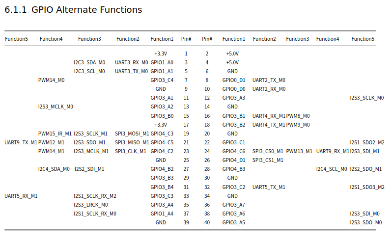
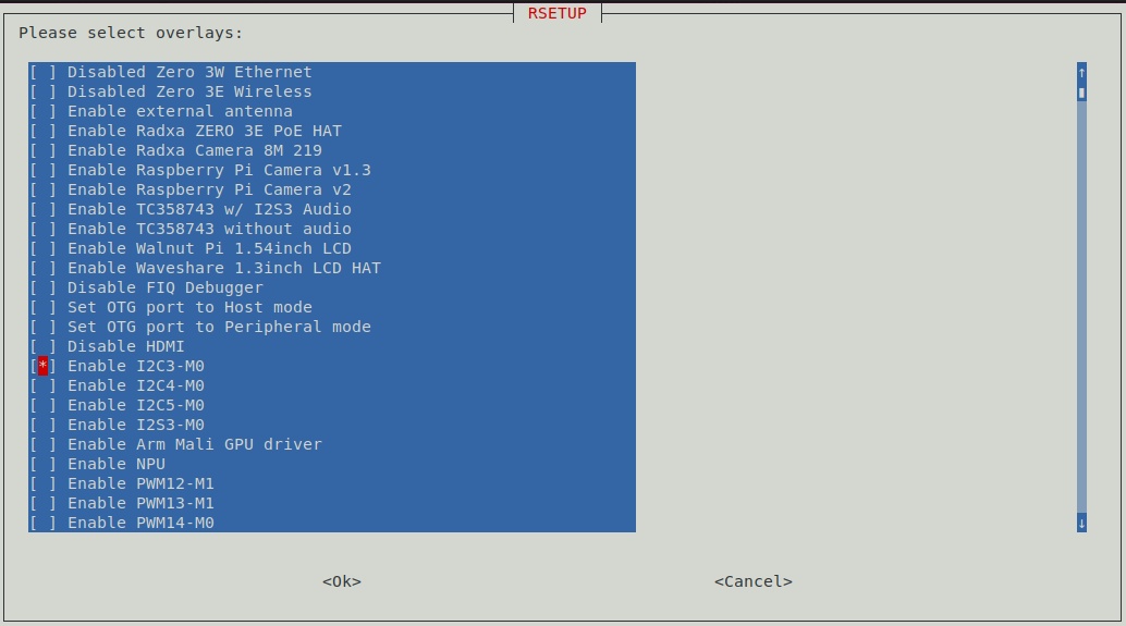
So pins 3 and 5 correspond to I2C3. To enable it, we use rsetup tool, “Overlays” => “Manage overlays”, select “Enable I2C3-M0”, then “ok” and reboot:
Connect the INA226 i2c to pins 3 (sda) and 5 (scl), then test if it was detected by the bus:
$ sudo i2cdetect -y 3
     0  1  2  3  4  5  6  7  8  9  a  b  c  d  e  f
00:                         -- -- -- -- -- -- -- --
10: -- -- -- -- -- -- -- -- -- -- -- -- -- -- -- --
20: -- -- UU -- -- -- -- -- -- -- -- -- -- -- -- --
30: -- -- -- -- -- -- -- -- -- -- -- -- -- -- -- --
40: -- -- -- -- 44 -- -- -- -- -- -- -- -- -- -- --
50: -- -- -- -- -- -- -- -- -- -- -- -- -- -- -- --
60: -- -- -- -- -- -- -- -- -- -- -- -- -- -- -- --
70: -- -- -- -- -- -- -- --
And use the following overlay:
$ nano ~/ina226-overlay.dts

/dts-v1/;
/ {
    fragment@0 {
        target-path = "/i2c@fe5c0000"; // Target the I2C bus that corresponds to i2c3
        __overlay__ {
            ina226@44 {
                compatible = "ti,ina226";
                reg = <0x44>; // I2C address of the INA226 from i2cdetect
                shunt-resistor = <100000>; // Shunt resistor value in micro-ohms (0.1 ohm)
            };
        };
    };
};
Compile and move it to /boot/dtbo/ directory and then run the following comand to turn it on:
rsetup enable_overlays ina226-overlay.dtbo $(cd /boot/dtbo/ && ls *.dtbo)Radxa Zero 3W kernel driver
By default, as of September 2025, Radxa don’t include the ina2xx driver in their kernel build. To find out if your system has this driver, try to run sudo modprobe ina2xx and if it fails, it means you don’t have the driver in your system. To build it:
sudo apt install linux-source-6.1 libssl-dev
sudo su
cd /usr/src
tar -xaf linux-source-6.1.tar.xz
cd linux-source-6.1
cp /boot/config-$(uname -r) .config  # or maybe `make oldconfig` ?
echo "CONFIG_SENSORS_INA2XX=m" >> .config
make prepare
make modules_prepare
make -j3 M=drivers/hwmon
cp drivers/hwmon/ina2xx.ko /lib/modules/$(uname -r)/kernel/drivers/hwmon/
sudo depmod -a